Microform Bend Deduction Calculator
Bend Formula Example
Bend Calculation Explained
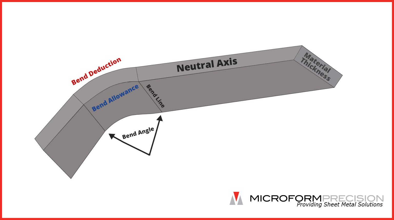
The white dashed line on the part shown above represents the neutral axis which is the theoretical point in the material that does not change during the course of forming. Material to the inside of this line ought to compress whereas the material on the outside of it should expand. The distance between the inside surface of the part and the neutral axis is known as the neutral axis offset. The K factor, in this case {{kFactor}}, expresses that distance as a percentage of the material's thickness. In other words, the neutral axis for this part occurs {{kFactor *100}}% of the way through the material's thickness. Given a thickness of {{thickness}}, that distance calculates to {{kFactor * thickness}}" ({{thickness}} x {{kFactor}}).
The bend deduction of " means that the material is expected to stretch by that amount during the course of bending. This is simulated on the part shown above by the section shown in red. " should be subtracted from the flat pattern so the formed part arrives at the desired dimensions. Because a bend deduction can be measured in a physical part, it is the most accurate way to calculate a material's stretch.
The bend allowance is the amount of the neutral axis that bends. In the example above, it is indicated by a dashed blue line. Although it is an option for calculating a bend in some CAD programs such as Solid Works, it is not often referred to in the actual manufacturing process since it is a theoretical number and cannot be verified in a physical part.